12 mar Risk Management Analysis
Access our free online tool for risk analysis and management!
Risk management analysis of structures due to lightning strikes is a complex topic, and many people end up making mistakes. The governing standard, ABNT NBR 5419:2015, presents a calculation methodology that is difficult to understand.
This article aims to provide the procedure for evaluating such risks according to the ABNT NBR 5419:2015 standard, but with a more didactic calculation sequence so that no one encounters problems during the execution of this analysis. Once the tolerable risk limit is chosen, the procedure presented below allows for the selection of appropriate protective measures to keep the risk within legal limits.
NBR 5419:2015 defines Protection Measures as the Atmospheric Discharge Protection System (ADPS) and Surge Protection Measures (SPM).
This standard provides the requirements for the protection of structures against physical damage through the use of an LPS (Lightning Protection System) and the protection of living beings against injuries caused by touch and step voltages in the vicinity of the LPS. It also includes protection of electrical and electronic systems, aiming to reduce equipment failures after a lightning strike.
According to the standard, risk is defined as the probable average annual loss in a structure due to lightning strikes, which depends on three main factors:
- The annual number of lightning strikes affecting the structure
- The probability of damage from a lightning strike
- The average amount of resulting losses
Lightning strikes can be divided into:
- Direct strikes to the structure
- Nearby strikes, either directly to connected lines (such as power or telecommunication lines) or near those lines
The ADPS includes both external and internal systems of the building and its contents, as well as the people inside. In general, it consists of the Atmospheric Discharge Protection System (ADPS) and Surge Protection Measures (SPM).
The ADPS (Atmospheric Discharge Protection System) is used to reduce physical damage to the structure caused by lightning strikes. On the other hand, SPM (Surge Protection Measures) are actions taken to protect internal systems and their contents against the effects of electromagnetic pulses resulting from lightning strikes.
To define the appropriate protection measures against lightning, a risk analysis must be carried out. This analysis should be performed by qualified and experienced professionals.
Each analysis is unique, even in similar buildings, there will be distinct characteristics that influence risk management, which makes it always necessary.
But how do you perform a risk analysis?
Keep reading, we’ll explain the procedures and calculations in detail, and at the end, you’ll find our calculator to assist you with these analyses.
Risk Management
The first step in conducting an accurate risk analysis is to gather relevant data and characteristics of the site, such as:
- Number of people who frequent the building
- Lightning ground flash density (1/km²/year) [NG]
- Dimensions of the structure (m) [L, W, H]
- Surge Protection Device (SPD) level in the installation (PEB)
- Building contents
- Lightning protection measures adopted
- Surge protection measures in place
- Nearby power or telecommunication lines
- Existing fire prevention and firefighting systems in the building
Once the building data is collected, we can begin our risk analysis by following the steps below:
Step 1: Analysis of Risk Components Due to Strikes on the Structure – Risk of Injury to Living Beings from Step and Touch Voltage (RA)
To calculate the risk due to lightning strikes on the structure, the following steps must be followed:
- Determine the length (L), width (W), and height (H) of the building and calculate the equivalent exposure area using the following expression:

- Definition of the Structure Location Factor (CD) According to the Table Below:
Table 1 – Structure Location Factor CD Source: ABNT – NBR 5419 (2015)
- Define the probability values (PTA) of a lightning strike to a structure causing electric shock to living beings due to dangerous step and touch voltages, according to the table below:
Table 2 – Probability Values PTA
 Source: ABNT – NBR 5419 (2015)
- Define the probability PB of a lightning strike to a structure causing physical damage, according to the table below:
Table 3 – Probability Values PB depending on protection measures to reduce physical damage Source: ABNT – NBR 5419 (2015)
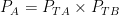
- Calculate the probability PA that a lightning strike to the structure will cause injury to living beings through electric shock, defined by the equation below:
- Define the typical average relative number of victims injured by electric shock (D1) due to a hazardous event, according to the table below:
Table 4 – Values of the typical average relative number of victims injured by electric shock (D1)
![]() Source: ABNT – NBR 5419 (2015)
Source: ABNT – NBR 5419 (2015)
- Define the human life loss reduction factor depending on the type of ground or floor surface, according to the table below:
Table 5 – Reduction factor rt based on ground or floor Surface type Source: ABNT – NBR 5419 (2015)
- Define the number of people in the zone (nz), total number of people in the structure (nt), and the time during which people are present in the zone, in hours per year (tz).
- Calculate the loss related to injuries to living beings from electric shock according to the following equation:

- Define the lightning flash density per km² per year (NG)
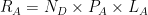
- Calculate the number of dangerous events (ND) for the structure according to the formula below:

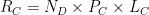
- Finally, calculate the component related to injuries to living beings from electric shock according to the expression below:
Step 2: Analysis of Risk Components Due to Strikes on the Structure – Component Related to Physical Damage (RB)
To calculate the risk of lightning strikes on the structure, considering physical damage, the following steps must be followed:
- Define the typical average relative number of victims injured by physical damage, according to the table below (D2):
Table 6 – Values of the Typical Average Relative Number of Victims Injured by Physical Damage
 Source: ABNT – NBR 5419 (2015)
- Define the loss reduction factor due to physical damage depending on the fire risk or explosion risk of the structure, according to the table below:
Table 7 – Reduction factor rf based on fire or explosion risk in the structure Source: ABNT – NBR 5419 (2015)
- Define the loss reduction factor (rp) due to physical damage depending on the measures taken to reduce the consequences of fire, according to the table below:
Table 8 – Reduction factor rp based on measures taken to reduce fire consequences Source: ABNT – NBR 5419 (2015)
Note: For structures with explosion risk, rp = 1 is considered in all cases.
- Define the loss increase factor (hz) due to physical damage when a special hazard is present, according to the table below:
Table 9 – Factor hz increasing the relative amount of loss in the presence of a special hazard Source: ABNT – NBR 5419 (2015)
- Once these values are defined, it is possible to calculate the loss related to physical damage LB in a structure according to the following equation:

- Finally, it is possible to calculate the component related to physical damage (RB) according to ABNT NBR 5419 (2015) as follows:
Step 3: Analysis of Risk Components Due to Lightning Strikes on the Structure – Component Related to Internal System Failures (RC)
To calculate the risk of lightning strikes on the structure, considering failures of internal systems, the following steps must be followed:
- Define the value of PSPD which depends on the coordinated Surge Protective Device (SPD) system and the lightning protection level (NP) for which the SPDs were designed. These values are provided in the table below.
Table 10 – Probability values of PSPD based on the NP level for which the SPDs were designed Source: ABNT – NBR 5419 (2015)
NOTE 1 – The values of PSPD can be reduced for SPDs that have better protection characteristics (higher nominal discharge current IN, lower protection level UP, etc.) compared to the requirements defined for NP I in the relevant parts of the installation.
- Define the values of the factors that depend on shielding, grounding, and insulation conditions of the line for lightning strikes on the line (CLD) or near the line (CLI), according to the table below.
Table 11 – Values of factors CLD and CLI depending on shielding, grounding, and insulation conditions Source: ABNT – NBR 5419 (2015)
- Calculate the probability (PC) of failures in systems. The calculation of PC must be carried out taking into account the lightning protection level (NP) for which the Surge Protective Devices (SPDs), in both power and telecommunication lines, were designed, as follows:


- Define the value of the typical average relative number (LO) of victims due to internal system failures caused by a hazardous event
Table 12 – Values of the typical average relative number of victims injured by internal system failures
 Source: ABNT – NBR 5419 (2015)
- Based on the data from the previous steps, it is possible to calculate the loss related to internal system failure (LC) due to lightning strikes on the structure, according to the equation below:

Where:
LO = Typical average relative number of victims due to internal system failure caused by a hazardous event
nz = Number of people in the zone
nt = Total number of people in the structure
tz = Time during which people are present in the zone, expressed in hours per year
- Finally, the risk component related to internal system failure due to lightning strikes on the structure is calculated according to the expression below:
Onde:
ND = Number of dangerous events for the structure
PC = Probability of system failures
LC = Loss related to internal system failure
Step 4: Analysis of Risk Components Due to Nearby Lightning Strikes – Component Related to Internal System Failure (RM)
The analysis of the risk component for internal system failure due to nearby lightning strikes is divided into two parts. The first considers the power line (RM/P), and the second takes into account the telecommunication line (RM/T).
To calculate the risk component from nearby lightning strikes, considering internal system failures, the following steps must be followed:
- Calculate the value of PMS according to the expression below:

Where:
KS1 = Takes into account the shielding efficiency provided by the structure’s mesh, the ADPS (Atmospheric Discharge Protection System), or other shielding at the protection zone interface
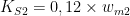
KS2 =Takes into account the shielding efficiency of internal mesh shielding within the structure at the protection zone interface
KS3 = Takes into account the characteristics of the internal wiring
KS4 = Takes into account the impulse withstand voltage of the system to be protected
Within a protection zone, at a safe distance from the edge of the mesh, at least equal to the mesh width wm, the factors KS1 and KS2 for the ADPS or spatial mesh-type shielding can be defined as follows:

Where:
wm1 and wm2 are the widths of the grid-type shielding, or the down-conductor spacing of the mesh-type ADPS, or the spacing between metal columns of the structure, or the spacing between reinforced concrete structures acting as a natural ADPS.
Note: The values of KS1 and KS2 are limited to 1. For a more conservative analysis, KS1 and KS2 are set equal to 1.
To define the value of the factor KS3 , use the table below:
Table 13 – Values of the factor KS3 depending on internal wiring Source: ABNT – NBR 5419 (2015)
The factor KS4 is defined as:

Where:
UW = Nominal impulse withstand voltage of the system to be protected, expressed in kilovolts (kV)
Note: Usually, the nominal withstand voltage value for power cables is 2.5 kV and for telecommunication cables is 1.5 kV. The maximum value of KS4 is limited to 1.
- After calculating the value of PMS and the value of PSPD in the previous step, the probability of system failure (PM) is calculated according to the equation below:
- The calculation of PM must be carried out taking into account the lightning protection level (NP) for which the Surge Protective Devices (SPDs) on the power and telecommunication lines were designed, as follows:


- Calculate the equivalent exposure area of discharges hitting near the structure, expressed in square meters (m²). The equivalent exposure area (AM) extending to a line located 500 meters from the perimeter of the structure is defined by:

Where:
L = Length of the building (m)
W = Width of the building (m)
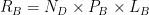
- Calculate the assessment of the average annual number of dangerous events (NM) due to lightning strikes near the structure according to the expression below:
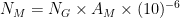
Where:
NG = Density of lightning strikes to the ground (1/km²/year)
AM = Equivalent exposure area of discharges hitting near the structure, expressed in square meters (m²)
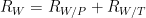
- Finally, the risk component related to internal system failure due to lightning strikes near the structure (RM) will be:

Step 5: Analysis of risk components due to line strikes – Component related to injury to living beings by electric shock (RU)
The analysis of the component related to injury to living beings by electric shock is divided into two approaches: the first considers the power line (RU/P), and the second considers the telecommunication line (RU/T).
For the calculation of the component related to injury to living beings by electric shock, the following steps must be followed:
- Define the line installation factor (CI) according to the table below:
Table 14 – Line installation factor CI Source: ABNT – NBR 5419 (2015)
- Define the line type factor (CT) according to the table below:
Table 15 – Line type factor CT Source: ABNT – NBR 5419 (2015)
- Define the environmental factor (CE) according to the table below:
Table 16 – Environmental factor of the line CE Source: ABNT – NBR 5419 (2015)
- Calculate the equivalent exposure area of discharges (AL) hitting the line, expressed in square meters (m²), according to the expression below:

Where:
LL = Length of the line in meters (m). If the length is unknown, consider LL equal to one thousand meters.
- Calculate the average annual number of dangerous events (NL) due to discharges on the line, according to the following equation:

Where:
NG = Density of lightning strikes to the ground (1/km²/year)
AL = Equivalent exposure area of discharges hitting the line
CI = Line installation factor
CE = Environmental factor of the line
CT = Line type factor
- Calculate the equivalent exposure area of the adjacent structure (ADJ) according to the expression below:

Where:
LJ = Length of the adjacent structure
WJ = Width of the adjacent structure
HJ = Height of the adjacent structure
- Define, based on the table below, the location factor (CDJ) of the adjacent structure:
Table 17 – Location factor of the structure CDJ Source: ABNT – NBR 5419 (2015)
- Calculate the number of dangerous events for the adjacent structure according to the equation below:

Where:
NG = Density of lightning strikes to the ground (1/km² × year)
ADJ = Equivalent exposure area of the adjacent structure
CDJ = Location factor of the adjacent structure
CT = Line type factor
- Define the probability value (PTU) of a discharge on a line entering the structure causing shock to living beings due to dangerous touch voltages, according to the table below:
Table 18 – Probability values PTU of a discharge on a line entering the structure causing shock to living beings due to dangerous touch voltages Source: ABNT – NBR 5419 (2015)
- Define the probability value (PEB) according to the level of protection against atmospheric discharges (NP) for which the SPD were designed, according to the table below:
Table 19 – Probability values of PEB according to the NPfor which the SPD were designed Source: ABNT – NBR 5419 (2015)
Note 1 – The values of PSPD can be reduced for SPDs that have better protection characteristics (higher nominal current IN, lower protection level UP, etc.) compared to the requirements defined for NP I in the relevant locations of the installation.
- Define the probability values (PLD) depending on the shielding resistance (RS) of the cable and the impulse withstand voltage (UW) of the equipment, according to the table below:
Table 20 – Probability values PLD depending on the shielding resistance RS of the cable and the impulse withstand voltage UW of the equipment Source: ABNT – NBR 5419 (2015)
- Calculate the probability (PU) of injury to living beings due to electric shock caused by lightning strikes near the connected line.

Where:
PTU = Probability of a lightning strike on a line entering the structure and causing electric shock to living beings due to touch and step voltages
PEB = Probability based on the protection level for which the SPDs were designed
PLD = Probability of internal system failure due to a lightning strike on the connected line
CLD = Factor depending on the shielding, grounding, and insulation conditions of the line (see Table 11)
- Calculate the loss (LU) related to injuries to living beings due to electric shock, caused by lightning strikes on the line, according to the following expression:

LT = Typical relative average number of victims injured by electric shock. See Table 4
nz = Number of people in the zone
nt = Total number of people in the structure
tz = Time during which people are present in the zone, expressed in hours per year
rt = Reduction factor of human life loss depending on the type of soil or floor. See Table 5
14. This analysis must be carried out for both the power line and the telecommunication line. Calculate the risk components related to injuries to living beings due to lightning strikes on the power line (RU/P) and on the telecommunication line (RU/T) according to the following expressions:


15. Finally, the risk component related to injuries to living beings due to lightning strikes on the line will be the sum of the components for the power line and the telecommunication line. Therefore:

Step 6: Analysis of Risk Components Due to Lightning Strikes on the Line – Component Related to Physical Damage (RV)
The analysis of the component related to physical damage due to lightning strikes on the line is divided into two approaches:
-
the first considers the power line (RV/P)
-
the second considers the telecommunication line (RV/T).
To calculate the component related to physical damage, follow the steps below:
- Calculate the probability (PV) of physical damage to the structure caused by lightning strikes on the line, according to the following expression:

Where:
PEB = Probability based on the protection level for which the SPDs were designed. See Table 19
PLD = Probability of internal system failure due to a lightning strike on the connected line. See Table 20
CLD = Factor depending on the shielding, grounding, and insulation conditions of the line. See Table 11
- Calculate the loss (LV) in a structure due to physical damage caused by a discharge on the connected line, according to the following equation:

Where:
rp = Loss reduction factor due to physical damage depending on measures taken to reduce the consequences of fire. See Table 8
rf = Loss reduction factor due to physical damage depending on the risk of fire or explosion in the structure. See Table 7
hz = Loss increase factor due to physical damage when a special hazard is present. See Table 9
LF = Typical average relative number of victims due to physical damage. See Table 6
nz = Number of people in the zone
nt = Total number of people in the structure
tz = Time during which people are present in the zone, expressed in hours per year
Note: The value of LV is equal to the value of LB
- This analysis must be performed for both the power line and the telecommunications line. Calculate the risk components related to physical damage due to discharges on the power line (RV/P) and on the telecommunications line (RV/T) according to the following expressions:


Where:
NL = Average annual number of hazardous events due to discharge on the line
NDJ = Number of hazardous events for the adjacent structure
PV = Probability of physical damage to the structure caused by discharges on the line
LV = Loss in a structure due to physical damage caused by a discharge on the connected line
- Finally, the risk component related to physical damage due to discharges on the line will be the sum of the components from the power line and the telecommunications line, therefore:

Step 7: Analysis of risk components due to discharges on the line — Component related to internal system failures (RW)
The analysis of the component related to internal system failures due to discharges on the line is divided into two approaches: the first considers the power line (RW/P), and the second considers the telecommunications line (RW/T).
To calculate the component related to internal system failures, follow these steps:
- Calculate the probability (PW) of internal system failures caused by discharges on the line, according to the expression below:

Where:
PSPD = Probability of reducing PC, PM, PW e PZ, when a coordinated SPD system is installed. See Table 10
PLD = Probability of internal system failure due to a discharge on the connected line. See Table 20
CLD = Factor depending on shielding, grounding, and insulation conditions of the line. See Table 11
- Calculate the loss (LW)due to internal system failure caused by discharges on the line, according to the following equation:

Lo = Typical average relative number of victims due to internal system failure caused by a hazardous event. See Table 12
nz = Number of people in the zone
nt = Total number of people in the structure
tz = Time during which people are present in the zone, expressed in hours per year
Note: The value of LW is equal to the value of LC
- This analysis must be performed for both the power line and the telecommunications line. Calculate the risk components related to internal system failures due to discharges on the power line (RW/P) and on the telecommunications line (RW/T) according to the expressions below:


Where:
NL = Average annual number of dangerous events due to discharge on the line
NDJ = Number of dangerous events for the adjacent structure
PW = Probability of internal system failure caused by discharges on the line
LW = Loss due to internal system failure caused by a discharge on the connected line
- Finally, the risk component related to internal system failure due to discharges on the line will be the sum of the component from the power line and the telecommunications line, therefore:
Step 8: Analysis of risk components due to discharges near the line — Component related to internal system failure (RZ)
The analysis of the component related to internal system failure due to discharges near the line is divided into two approaches: the first considers the power line (RZ/P) and the second considers the telecommunications line (RZ/T).
For calculating the component related to internal system failures, follow the steps below:
- Define the value of the probability (PLI) of internal system failure due to a discharge near the connected line, depending on the characteristics of the line and the equipment, according to the table below:
Table 21 — Values of probability PLI depending on the type of line and the equipment’s impulse withstand voltage UW  Source: ABNT – NBR 5419 (2015)
- Calculate the probability (PZ) of internal system failures caused by discharges near the line, according to the expression below:

Where:
PSPD = Probability of reducing PC, PM, PW e PZ, when a coordinated SPD system is installed. See Table 10
PLI = Probability of internal system failure due to a discharge near the connected line
CLI = Factor depending on shielding, grounding, and insulation conditions of the line. See Table 11
- Calculate the loss (LZ) due to internal system failure caused by discharges near the line, according to the following equation:
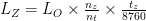
Lo = Typical average relative number of victims due to internal system failure caused by a hazardous event. See Table 12
nz = Number of people in the zone
nt = Total number of people in the structure
tz = Time during which people are present in the zone, expressed in hours per year
Note: The value of LZ is equal to the value of LC
- Calculate the equivalent exposure area (AI) of discharges to ground near the line, expressed in square meters (m²), defined by:
Where:
LL = Length of the line section, expressed in meters (m).
- Calculate the number (NI) of overvoltages with amplitude not less than 1 kV (1/year) in the line section, according to the following expression:

Where:
NG = Density of lightning strikes to ground (1/km²/year)
AI = Equivalent exposure area of discharges near the line
CI = Line installation factor. See Table 14
CE = Line environmental factor. See Table 16
CT = Line type factor. See Table 15
- This analysis must be performed for both the power line and the telecommunication line. Calculate the risk components related to internal system failures due to discharges near the power line (RZ/P) and near the telecommunication line (RZ/T) according to the expressions below:

Where:
NI = Number of overvoltages with amplitude not less than 1 kV (1/year) in the line section
PZ = Probability of internal system failure caused by discharges near the line
LZ = Loss due to internal system failure caused by a discharge near the connected line
- Finally, the risk component related to internal system failure due to discharges near the line will be the sum of the component from the power line and the telecommunications line, therefore:

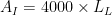
Step 9: Calculation of economic losses (L4)
The loss value for each zone can be determined according to Table 22 below, considering that:
- Economic loss is affected by the characteristics of the zone. These take into account the reduction factors (rt, rp, rf);
- he maximum loss value due to damage in the zone must be reduced by the ratio between the relevant value in the zone versus the total value (ct) of the entire structure (animals, building, contents, and internal systems including their activities). The relevant value of the zone depends on the type of damage:
– D1 (injuries to animals due to electric shock): ca + cb + cs (total of all values);
– D2 (physical damage): ca + cb + cc + cs (total of all values);
– D3 (internal systems failure): cs (value of internal systems and their activities).
Table 22 – Type of loss L4: loss values for each zone Source: ABNT – NBR 5419 (2015)
Where:
LT = is the typical relative average value of all values damaged by electric shock due to a hazardous event. See Table 23.
LF = is the typical relative average value of all values affected by physical damage due to a hazardous event. See Table 23.
LO = is the typical relative average value of all values damaged by internal systems failure due to a hazardous event. See Table 23.
rt = is a loss reduction factor for animals depending on the type of soil or flooring.
rp = is a loss reduction factor due to physical damage depending on the measures taken to reduce the consequences of fire. See Table 8.
rf = is a loss reduction factor due to physical damage depending on the fire or explosion risk in the structure. See Table 7.
ca = is the value of animals in the zone.
cb = is the value of the building relevant to the zone.
cc = is the value of the contents of the zone.
cs = is the value of internal systems including their activities in the zone.
ct = is the total value of the structure (sum of all zones for animals, building, contents, and internal systems including their activities).
If economic values for the zones are not available, the ratios ca/ct, (ca + cb + cc + cs)/ct, and cs/ct, present in Table 22, should be considered as unitary.
Table 23 – Loss type L4: Typical average values of LT, LF e LO Source: ABNT – NBR 5419 (2015)
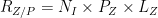
Step 10: Calculation of Risk Components
To calculate the risk components to be considered for each type of loss in the structure, follow the steps below:
- Calculate the risk (R1) of loss of human life as follows:

Note: For structures without explosion risks, hospitals, or other structures where internal system failures may endanger human life, the indices RC, RM, RW e RZ are zero.
- Calculate the risk (R2) of public service losses using the following expression:

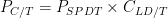
- Calculate the risk (R3) of losses to cultural heritage service, defined by the following equation:

- Calculate the risk (R4) of economic value losses using the expression below:
The calculations of losses LA, LB, LC, LM, LU, LV, LW and LZ must be performed according to the formulas presented in Table 22.

Note: For properties where there is no risk of animal losses, the indices RA and RU are zero.
- Compare the calculated risk values above with the tolerable risk (RT) from the table below:
Table 24 – Typical values of tolerable risk RT Source: ABNT – NBR 5419 (2015) – Adaptado
If the calculated risk is equal to or less than the tolerable risk (R ≤ RT), lightning protection is not required.
If the calculated risk is greater than the tolerable risk (R > RT), protective measures must be adopted to reduce all risks to which the structure is subject so that the condition (R ≤ RT) is satisfied.
Pingback:Artigo Eng. Victor Merlin: Análise do gerenciamento de risco | MONTAX ENGENHARIA DO PROPRIETÁRIO – OWNER ENGINEERING
Postado em 19:00h, 16 julho[…] Análise do gerenciamento de risco […]